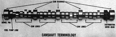
Installing a Racing Camshaft
A racing camshaft is a precision product that requires tender loving care in its installation. Probably anyone with some natural feel for mechanics can install a racing camshaft, especially if he is careful and observant, before and during the removal of the stock camshaft.
Before removing the stock camshaft, revolve the crankshaft slowly a few turns and notice the position of the timing marks on the cam and crank sprockets, with the No. 1 cylinder piston at T.D.C. (Top Dead Center). Be sure that when installing your new camshaft you align these timing marks in the same, position (see Fig. 1 or consult your motor manual). If these timing marks are not aligned properly during assembly, the camshaft will be out of phase with the crankshaft and the valves may be damaged if they strike the pistons.
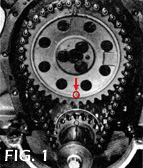
*Shown is the procedure for aligning timing marks on a 427-cu-in. Chevy; however, procedures vary from engine to engine.
If you cannot find the timing marks, DO NOT remove the camshaft - consult a motor manual.
After removing the timing chain and lifters, place the cam sprocket back on the camshaft and revolve the cam in the block by hand and observe how freely it turns. Your racing cam should also turn this freely in the block, when installed correctly. Before installing your new camshaft, the part numbers of the camshaft and valve gear components should be checked to coincide with those in this catalog, to avoid any mismatch of equipment in the event of a shipping error. The camshaft and all valve gear components should be washed in solvent (with the exception of hydraulic lifters which will become contaminated) and dried thoroughly. Coat the cam lobes and bearings with the Isky Cam Lube Oil Conditioner supplied with the cam, and carefully revolve the cam while inserting it through the block, taking care not to score the cam bearings.
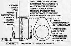
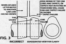
Assemble the timing chain and cam sprocket while aligning the timing marks properly, and torque the cam sprocket bolt or bolts to the proper specifications. Next, lubricate and install the lifters, always using a new set of lifters, for proper tappet-to-cam-lobe contact (Fig. 2). Also check each lifter in its bore for free unrestricted movement. If any of the lifters do not rotate freely in their bosses, the contact pattern between the cam and lifter face will not be properly distributed, and this can result in cam and lifter failure (Fig. 3).
ASSEMBLING VALVE SPRINGS AND CHECKING FOR INTERFERENCE
The next step is checking for interference in the valve gear, and its importance cannot be overemphasized. Any one of the following conditions can cause severe cam and lifter wear, as well as damage to the other valve gear components. Remember, good judgment and common sense are necessary here, and when in doubt, consult your motor manual or someone with more experience than yourself. These interferences are:
- Spring retainer-to-valve guide interference.
- Valve spring coil bind (stacking solid).
- Rocker arm-to-stud interference (on engines equipped with ball-stud rockers).
- Piston-to-valve interference (V/P clearance).
THE CHECK FOR RETAINER-TO-GUIDE INTERFERENCE
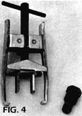
This is a simple procedure and is easily done on a workbench. However, if the engine is in the car, and you wish to remove the springs without removing the cylinder heads, you can purchase the Isky valve spring removal kit (Fig. 4)containing a spark plug fitting that allows the valve to be held up on its seat with shop air pressure, while you compress and remove the valve spring, using the companion clamp tool. After removing the stock spring, place the new spring retainer and split locks back on the valve and pull up on the retainer, to simulate the tension of the valve spring. Now, measure the amount of free travel between the top of the guide and the bottom of the retainer. This measurement should be sufficient to cover the full valve lift of your camshaft plus 1/16-inch to 1/8-inch extra safety margin (Fig. 5). Next check the installed height (fitted dimension), that the valve spring will assume when installed on the cylinder head (Fig. 5A).Be sure the dimension is identical within 1/32-inch to the dimension supplied with the valve springs. If it is longer, the supplied spring shims will correct this dimension. Note: All Iskenderian Hydraulic and Hi-Rev Series valve springs install like stock springs and require no machining of the cylinder heads. However, our Hardface Overlay and Roller tappet camshafts come equipped with heavy-duty inner springs and larger diameter outer springs, and on some engines it's necessary to use a counter-boring hole saw cutter to re-machine the spring seats on the cylinder heads, for their acceptance.


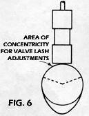
Now proceed to assemble the springs on the cylinder heads, and also install the pushrods and rocker arms. Adjust the valve lash to the proper specifications, being certain that the lifter is on the heel of the cam lobe each time (Fig. 6).

ISKENDERIAN METHOD OF MEASURING PUSHRODS
The proper method of measuring the length of pushrods is to include the theoretical overall length, however, this is difficult for the average individual since special equipment is required. In the interest of accuracy and to avoid confusion, we have adopted the above method of measurement. This eliminates the difficulties that arise when making measurements in the field, or when installing special length pushrods (custom made on special order for our customers).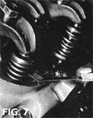
THE CHECK FOR VALVE SPRING STACKING SOLID (COIL BIND)
To insure that your valve springs are not stacking solid (which will destroy your valve train), rotate the engine over slowly to the full lift position of the intake and exhaust valves and look for air space between the coils. If you cannot tell by eye, verify by inserting a .010- inch feeler gauge between the coils (Fig. 7). A .010 space between five coils would give a total of .050 safety margin before stacking solid. If you cannot pass the feeler gauge between the coils, the spring is either coil bound or dangerously close to this condition, and you have probably overshimmed the spring (the fitted dimension is too short). Remove the unnecessary shims and recheck the fitted dimension, and for a coil bound condition of the spring.
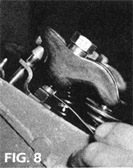
THE CHECK FOR ROCKER-TO-STUD INTERFERENCE
Where engines are equipped with ball stud rocker arms, even experienced mechanics have difficulty in detecting this dangerous condition. However, accurate detection can be made by the Isky probe method - by probing the area between the rocker arm slot end and the stud with an appropriately bent paper clip or wire solder at both valve open and closed positions (Fig. 8). If there is insufficient clearance here, it will be evidenced by the pinching of the wire probe or clipping off of the wire solder, thus indicating that the slot in the rocker arms must be lengthened on the appropriate side or sides by grinding with a grinder and a 3/8-inch-diameter stone.
HOW TO CHECK FOR CLEARANCE BETWEEN VALVES AND PISTONS
It's the engine mechanics' responsibility to check the V/P clearance when building an engine. This information should be furnished to the customer along with piston clearances, bearing clearances, spark lead, etc., in an "Engine Data Form." Even "big name" racers have questioned us regarding total valve lift on a certain camshaft, so they could notch, or "eyebrow," their pistons accordingly. This is not a pertinent question, since "total valve lift" is not the criterion for V/ P clearance ... because, when total valve lift occurs, the piston is more than half-way down the cylinder. Therefore, the proper phrasing of the question should be, "How far are the valves open at T.D.C. with the cam in the split-overlap position?" For only when the piston is in the immediate 'vicinity of Top Dead Center is there a danger of V/ P interference (valves striking pistons). Of course, this occurs only every other revolution of the crankshaft during the overlap period, when both intake and exhaust valves are partially open.
In the old days, the first four-cycle engine had very short valve timing by today's standards. The valve timing then was: intake valve opens at T.D.C., and as the piston lowers, it draws in the fuel/air mixture; the intake valve then closes at (B.D.C.) hence, the intake stroke. The piston rises, with both valves closed to compress the fuel/air mixture - . . hence, the compression stroke. The spark plug fires and ignites the fuel/air mixture which drives the piston down to B.D.C. (again the valves are closed) hence, the power stroke. Also, the exhaust valve opens at B.D.C. The burnt gases, due to their high pressure, virtually expel themselves, and the piston drives the last of the gases out; the exhaust valve closes at T.D.C. . . . hence, the exhaust stroke. These early engines had 0° overlap or no overlap whatsoever.
By experimentation, the more progressive cam engineers of the 1910's and 1920's discovered that the mid-range and high-speed power could be greatly improved by lengthened valve timing. The stretching of the intake valve timing allowed the engine to breathe deeper and take in greater amounts of air and fuel, thus creating a more powerful explosion in the combustion chamber.
An important advantage gained from lengthened exhaust valve timing is that the greatly expanded burnt gases are eliminated more efficiently. Unless these burnt gases are completely expelled from the combustion chambers, they will remain to displace and contaminate the incoming fresh fuel/air charge.
Lengthening of valve timing in the gasoline engine brought on overlapping of the intake and exhaust valve events. (Both intake and exhaust valves are slightly open at T.D.C., and for up to 60 degrees on either side of T.D.C. on a radical cam.)
In the early days, any unintentional overlapping was considered detrimental. But much later, it was discovered that a mild supercharging effect could be obtained from the overlap event when an optimum exhaust system was used. Thus, the overlap event created a new 'fifth cycle" in the four-cycle engine.
It will prove to be both practical and more economical to make your check of the V/P clearance in the early stages of engine building. Otherwise, it may be necessary to tear down a complete engine for piston machining, should the V/P clearance check prove inadequate. When it does, it could involve costly rebalancing of the rotating and reciprocating components.
CHECKING V/P CLEARANCE BY THE "CLAY METHOD"
Obtain some child's modeling clay and work it between the palms to the size of a pat of butter and approximately 1/4-inch thick. Place these clay pads in the "eyebrows" (the machined relief pockets) where the intake and exhaust valves could strike the piston (see Fig. 9).
The cylinder head with gasket is now placed in position, and held down with only two or three bolts. After adjusting the valve lash, the engine is now rotated clockwise through at least two crankshaft revolutions to assure cycling through one overlap event. Now, remove the cylinder head, and observe the impression made by the valves on the clay pads, as shown in Fig. 10. By measuring the compressed thickness of the clay with a machinist's scale or micrometer, you can determine the valve-to-piston clearance of the intake and exhaust valves.
It is important to look for the following - any one of these "symptoms" will cause problems: "eyebrows" that are dislocated on the piston crown; cut on the wrong angle; or notched for a smaller valve diameter than the valve size now employed.


THE ISKY "LIGHT SPRING" METHOD OF CHECKING V/P CLEARANCE
In this procedure, Isky employs two light compression springs on the intake and exhaust valves of the No. 1 cylinder. These springs resemble normal racing springs except that they are quite weak by comparison, exerting only 10 pounds load. The gasket and cylinder head are installed with two or three bolts. Tappets, pushrods and rocker arms are then installed for the No. 1 cylinder, and the valve lash is adjusted. The crankshaft is revolved and stopped at T.D.C., with intake and exhaust valves partially open in overlap position.
WHAT IS THE V/P SAFETY MARGIN?
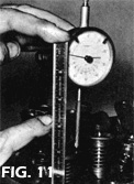
The next procedure is to determine the unseen safety margin (space) remaining between these partially opened valves and the piston crown in its uppermost T.D.C. position. If clearance is insufficient, severe damage may result during high-speed operation when the valves literally play tag with the piston. Since we have installed light 10-pound springs instead of regular 200-pound valve springs, the V/P clearance can be checked by merely applying thumb pressure, as shown inFig. 11.
By placing a machinist's scale, or mounting a dial indicator, at the side of the spring retainer, as shown in Fig. 11, we can now exert thumb pressure on the rocker arm and feel the valve head make contact with the piston crown. By observing the movement of the valve at the machinist's scale, or reading the dial indicator, the V/P clearance may now be determined. Caution: Check valve-to-piston clearance five to 10 degrees on either side of T.D.C., because in some instances (due to piston dwell and valve velocity) the valves may be in closer proximity to the piston when slightly off from T.D.C. In case of valve toss (float) due to over-revving, the exhaust valve is always the first to make contact with the piston. Since it is closing as the piston is rising, any discrepancy in following the dictates of the cam profile may cause contact with the piston. A good mechanic will always look for exhaust valve contact when disassembling an engine.
WHAT IS CONSIDERED SUFFICIENT V/P CLEARANCE?
Ideally, we would like .250 clearance, or even more, but this cannot be obtained in today's racing engine, except in low compression (6:1) supercharged engines. In normally aspirated racing engines, compression ratios of 10 to 12:1 must be employed to obtain maximum power. Consequently, high-dome pistons are mandatory. These high domes invade the domain of our valuable valve operating space. And, even after machining valve reliefs (eyebrows), we are forced to compromise for less V/P clearance than is desirable. Consequently, in today's normally aspirated high-compression engines, we are settling for .125-inch V/P clearance, and in difficult situations, getting by with as little as 100 V/P clearance. If aluminum connecting rods are employed, the engine builder should allow for an additional .020 due to heat expansion.
We have now covered the four forms of valve gear interference and are ready to start the engine. Before starting, however, observe the following important rules. Be sure that:
- Oil level in pan is up to mark.
- Cooling system is full.
- No obstructions (tools, parts, etc.) are in the way of the fan or crankshaft.
- Battery is fully charged.
- There is fuel in carburetor.
Steps No. 4 and 5 are most important because you should avoid overcranking the engine before firing. If possible, prime the oil system by turning the oil pump shaft with a speed wrench until pressure is indicated on the oil gauge.
Start the engine and immediately rev it to 2500-3000 rpm. Do not idle the engine for the first 15 minutes of operation. This is necessary to allow full oil pressure in the engine to lubricate the cam and lifters during this very critical mating-in period. Remember that running the engine at this rpm and using Isky Cam Lube during this critical mating-in period insures you of many years of trouble-free service.
One last point: When using our Hydraulic or Hi-Rev Series camshafts, always use a quality detergent oil clearly labeled MS-DG. This is particularly important when using hydraulic lifters as detergent oil prevents the varnish build-up which can cause sticking in hydraulic lifters. Detergent oil is used in all new automobiles equipped with hydraulic lifters and is available at all service stations. With our Hardface Overlay and Roller tappet camshafts, a racing grade of non-detergent oil is preferable because of its improved lubricating properties at high engine speeds.
TIMING THE CAMSHAFT
Because Iskenderian cams are manufactured with such high precision, you can install them on the stock timing marks without any further checking; however, for those who wish to learn how to properly check and verify valve timing, we recommend the following procedure.
HOW TO FIND TOP DEAD CENTER
Finding absolute Top Dead Center (T.D.C.) is the most important step in timing a camshaft. And trying to operate an engine without this vital marker is like trying to read a tachometer without an indicator needle. The T.D.C. marker is the all-important datum (tuning) point from which all ignition and valve timing is based. Quite often, we have observed racers at Bonneville, drag strips and circle tracks who neglected to provide themselves with a T.D.C. marker. All stock engines have a stationary pointer affixed to the block, and a T.D.C. marker on the crankshaft harmonic balancer. But, these racers lost the original pointer when they changed to an aluminum timing gear cover. Or, on supercharged engines, when they changed to a steel crankshaft drive hub, they lost the original T.D.C. marker. Now, here is their predicament: they now have no way of accurately setting their spark lead or valve timing. Had this engine been accurately calibrated for T.D.C. by utilizing the 'Isky Positive Stop Method" while still on the bench, all doubts and frustrations would have been avoided. Thus, a possible winner became a loser.
It is a common error to miss T.D.C. by a few degrees due to the piston dwell at top center. Inasmuch as this inaccuracy will substantially affect subsequent timing, the following procedure is suggested to correct this error.
- Mount degree wheel on the front of the crankshaft. Now bolt a stationary pointer on the cylinder block (see illustration). Pointer can be made of metal strip or ¼-inch steel rod.
- Mount a dial indicator securely to the cylinder block. Now adjust dial so that at maximum piston rise the indicator sweep hand travels through approximately .300 of movement. The dial indicator contact point should rest on the center of the piston.
- Now to turn crankshaft over, use a long-handle wrench or lever so as to get an even, steady movement and not a jerky motion. The crankshaft should always be rotated in the normal running direction.
- . Holding your thumb down on the No. 1 piston (to eliminate all lash), come up slowly to T.D.C. until you reach what you guess to be the middle of T.D.C. dwell. Set your degree wheel to read T.D.C. against the pointer.
- Now rotate crankshaft one more revolution and this time on the way up to T.D.C., stop exactly .200 (dial indicator reading) below the maximum piston travel. Now read the degree wheel: if, for example, it reads 40 degrees before T.D.C., continue rotating slowly on up to T.D.C., over the hump and down the other side, keeping thumb firmly on piston. Watch dial indicator closely, and when it reads exactly .200 down from T.D.C., stop and note reading on degree wheel. If you have a perfectly split overlap, it should read 40 degrees after T.D.C. If it doesn't, you have not found exact T.D.C., therefore, you must try again.
MAKING CORRECTIONS
Split the difference (your error in degrees) by moving the degree wheel radially on the crankshaft. After you have made the adjustment, come around with the crankshaft as before, stopping .200 below each side of T.D.C. When you get exactly the same degree readings .200-inch below each side of T.D.C., you have found absolute lop Dead Center. NOTE: The exact travel of .100-inch below T.D.C. is not important. Any check point between .100 and .500 will give good results, as long as you check each side of T.D.C. equidistantly.
POSITIVE STOP METHOD OF FINDING T.D.C.
The most practical way of locating T.D.C. is known as the positive stop method. No dial indicator is required for this procedure. First, let's see how it's done, utilizing the degree wheel.
- Fasten the degree wheel to the crank. Then, take a stiff 1/4-inch rod or similar material and sharpen one end to form a pointer. Attach this pointer so that it rests very close to the damper to eliminate parallax viewing error.
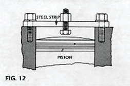
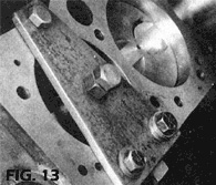
- Obtain a stout strip of steel about seven inches long and drill three 1/2-inch holes in it (see Fig. 12 & 13 for position of holes). This strip is placed across the center of the No. 1 cylinder bore and bolted on each end to secure it to the block. Caution: Be sure that the strip of steel is rigid enough so that it will not be deflected when the piston contacts the center bolt stop. Incidentally, the positive stop should be adjusted so as to stop the piston's upward travel at approximately .200 to .800 below T.D.C.
- Rotate the crankshaft in normal running direction (clockwise) until the piston crown lightly strikes the positive stop.
- Now, radially adjust and lock the degree wheel to the crankshaft at 40 degrees before T.D.C. at the pointer.
- Now rotate the crankshaft backwards to the positive stop. If the degree wheel reads 40 degrees from T.D.C., you have hit lop Dead Center exactly, and the zero mark between the two 40- degree readings is absolute T.D.C.
- However if your readings were Unbalanced, you will have to split the difference (your errors in degrees) by moving the degree wheel radially on the crankshaft. Then, try again until you get exactly the same degree readings against the positive stop on either side of T.D.C. NOTE: The lower the positive stop is located below T.D.C., the greater the degree readings will be. But, the results will always be accurate. T.D.C. always lies equidistant between the two positive stop readings.
FINDING T.D.C. ON YOUR HARMONIC DAMPER WITHOUT DEGREE WHEEL
Even without the degree wheel, you can and always should calibrate the T.D.C. mark on your harmonic damper when building or assembling a new engine. By using Step No. 3 and No. 5, each time you contact the positive stop, rotating both forward and backward, scribe a mark on the damper in line with the pointer. T.D.C. will be exactly between the two scribed stop marks. Carefully measure and scribe a permanent T.D.C. marker between these two stop marks. Remember the T.D.C. marker is the important datum (tuning) point from which all ignition and valve timing is based.
CHECKING THE CAMSHAFT
Having determined T.D.C. and using your degree wheel and 1/2-inch travel dial indicator, you are now ready to proceed with degreeing-in your camshaft. The first rule is that a camshaft must always be checked at the lifter and never at the valve. This is important since production tolerances on stock rocker arms can confuse your readings at the valve, whereas the direct motion of the lifter on the cam lobe will be the same for each lifter in the block. Another reason for never checking at the valve is that a rocker arm's theoretical ratio, usually 1.5:1, is true only at approximately mid (1/2) valve lift. The ratio varies from slightly more to slightly less than 1.5:1 through the lifting cycle, because the rocker arm continually varies its point of contact on the valve stem.
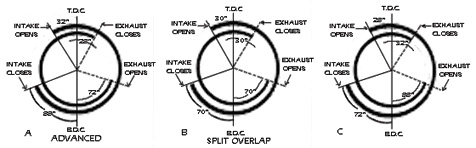
The purpose of checking the camshaft in the block is to determine whether the camshaft is installed in the correct relationship (or phasing) with the crankshaft. Generally speaking, most cams perform best at split overlap, because they give their best all-round performance in this position. Split overlap means that the intake and exhaust valves are equally open at T.D.C., although the intake valve is opening and the exhaust valve is closing. Also this means that the intake valve opens the same number of degrees before T.D.C., as the exhaust valve closes after T.D.C. A cam in the advanced position would have its intake valves open further at T.D.C. than the exhaust valves, and also open at a greater number of degrees before T.D.C. than the exhaust valves close after T.D.C. Conversely, a cam in the retarded position would have its exhaust valves open further at T.D.C. than the intake valves, and also close at a greater number of degrees after T.D.C. than the intake valves open before T.D.C. Also, remember that a cam turns at 1/2 the speed of the crank; consequently two degrees of crank rotation is equal to one degree of cam rotation, and two degrees of crank advance will equal one degree of cam advance. Always use a new timing chain when installing or checking the timing on a new camshaft. An excessively stretched chain can retard cam timing, as much as four cam degrees, because of the slack in the links. Also, even though most of the valve timing figures in this catalog are listed at split overlap, most of our camshafts are ground from one to two cam degrees advanced to allow for eventual stretch in the timing chain. Therefore, if upon timing your camshaft you find it to be one to two degrees advanced at the cam, it should be left in this position because subsequent stretch of the timing chain will retard the timing slightly and it will be closer to split overlap.
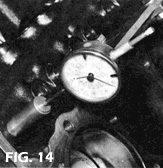
To begin your check of the camshaft, rotate the crankshaft until the No. 1 cylinder intake tappet is on the base circle (heel) of the cam lobe. Lubricate the tappet with light oil and check to see that it has free, unrestricted movement in the bore. Position the dial indicator stem parallel to the lifter in both planes, and pre-load the indicator's stem .050-.100 on the tappet. At Iskenderian to facilitate checking, we use an extended tappet which brings the tappet to the proximity of the head gasket face and provides a level surface for the stem of the dial indicator (Fig. 14). Rotate the crankshaft clockwise several times to determine the runout or eccentricity of the base circle. This should not exceed .001 and should be centered equally on both sides of the zero on the dial indicator.
The timing tag you received with your camshaft shows the timing as determined by Iskenderian engineers at a specific checking height off the base circle. This height is indicated on the tag and is usually between .017 and .023 depending on which specific cam you have. For example, let's assume the valve timing is as follows:
 |
For typical 280 degrees duration camshaft:
|
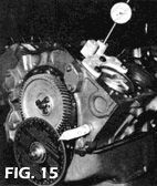
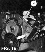
Assuming the checking figure is .020, rotate the crankshaft clockwise until .020 dial indicator movement is detected and read the degree wheel opposite the stationary pointer. It should read 30 degrees before T.D.C. (Fig. 15). Record this reading and continue rotating the crankshaft, watching the lifter reach full lift and begin its descent and stop the crankshaft movement at .020 indicator reading before zero on the closing side of the cam lobe. The reading should be 70 degrees after B.D.C. (Bottom Dead Center of piston travel -Fig. 16).
The total duration of the opening period then, was 30 degrees before T.D.C. plus 180 degrees to B.D.C. plus 70 degrees after B.D.C., or 280 crankshaft degrees. Using this same procedure, check the exhaust lobe of the same cylinder and record your readings. If the opening and closing points of the camshaft vary, but the total duration figure is correct or within two crankshaft degrees, the camshaft is slightly out of phase with the crankshaft (slightly advanced or retarded as explained earlier). Aside from timing chain stretch and the slight amount of advance built into the cam, this condition may also be caused by the slight errors in the crankshaft or crank sprocket keyway location, or in the key or dowel pin hole of the cam sprocket. These slight errors may either accumulate or cancel each other out, but if they accumulate they can vary the cam timing as much as two crankshaft degrees. An example of this is shown here.
The above-mentioned checking procedure will produce fairly accurate results if all conditions are perfect - tappet bores not excessively worn, dial indicator in an absolute parallel plane with the lifter to avoid any cosine errors, absolute T.D.C. determined, and an experienced operator performing the check.
However, to really accurately determine the position of your camshaft in the engine, it is advisable to use a wider checking clearance of .050 off the base circle for the following reasons:
- At .020 lift off the base circle the lifter is still moving at a very slow rate in relation to crankshaft movement, and a checking height error of only .001 can change your degree wheel reading as much as five crankshaft degrees.
- However, at .050 lifter rise a .001 error in checking height would only affect your degree wheel reading about 1/2 crank degree because the lifter is moving much faster in relation to crank rotation.
Therefore, the professional engine builder checks his camshafts at this .050 rise to eliminate all possible errors. The procedure for checking at this height is the same as mentioned earlier; however, the camshaft will appear to be very short in duration because you are checking higher up on the cam flank, and not really checking the actual valve seat timing.
For your convenience the timing for the .050 lifter rise check is also shown on the timing tag.
CHECKING VALVE OVERLAP WITHOUT DEGREE WHEEL OR DIAL INDICATOR
When installing a camshaft, or when an occasion arises where it is necessary to make a check on valve timing and no appropriate instruments are available, the recommended Isky procedure is as follows:
- Insert the camshaft and mesh the timing gears on the stock marks. Do not as yet install the timing gear cover.
- Using a long wrench or lever, turn the engine over in the normal running direction. Use enough leverage to get an even, steady movement instead of a jerky motion. Rotate until the intake and exhaust valves of No. 1 cylinder are in the overlap position (both valves opened slightly). Stop exactly on T.D.C., which is marked on the harmonic damper.
- Now loosen and back off the rocker arm adjusting screws until the intake and exhaust valves are just barely closed. Lock the tappet adjustment screws so that the intake and exhaust valves are at exactly zero clearance.
- Now turn the engine over exactly one revolution of the crankshaft to T.D.C. on the harmonic damper. You are now at T.D.C. on the compression or firing stroke.
- Take notice! Now there is a large space between the rockers and valve stem tips. This space indicates the actual amount the valves were open at T.D.C. of the overlap period (less valve lash, of course).
- We will measure this gap space by probing with common feeler gauges of various thicknesses combined until we determine the gap space. After computing the gap, record the figures for both intake and exhaust in your notebook. If the amount of gap on intake and exhaust is exactly the same, you have a perfect split overlap.
AN EXAMPLE USING AN RPM 300 CAM
Advanced Cam Position: If your intake happens to come out with .100 gap, and the exhaust with say .080 gap, your cam is in an advanced position. In this position, the cam will produce more low-speed power or torque. However, there might be a slight loss of power at high rpm.
Retarded Cam Position: If, on the other hand, the intake came out with .080 gap, and the exhaust at .100, your cam is in a retarded position. In this position, there will be some loss in low-speed torque and power, and probably some subsequent gain in high-speed power.
Split Overlap: If intake and exhaust gap read out exactly even, or within .005 of each other, you have a split overlap. Generally speaking, all racing cams run best in the split overlap position. While there are exceptions to this rule, it is usually best for overall performance.
Finally it should be noted that sometimes it is desirable to advance or retard the camshaft from two to eight degrees to make the engine perform better at certain engine speeds. Generally speaking, advancing the camshaft increases low speed and mid-range torque while causing high-speed power to suffer slightly. Retarding the camshaft usually provides an increase in top-end power and consequently a slight loss in low-speed and mid-range torque.
We manufacture various offset bushings and offset keys (Fig. 17) which will change your cam timing to either correct slight errors in sprocket or crank keyway location, or to provide the above-mentioned changes in the power output curve to suit various operational or race track conditions. Whether using our offset cam bushing or cam keys, the thing to remember is that with chain driven camshafts, move -the cam itself clockwise in relation to its sprocket to advance the cam and counterclockwise to retard the cam (Fig. 18). With gear-driven camshafts that revolve in the opposite direction of the crankshaft, move the cam itself counterclockwise in relation to its gear to advance the cam and clockwise to retard the cam timing. Also, when using our offset bushings, it is necessary to drill the dowel pin and bolt holes in the cam sprocket oversize, as specified in the instructions.

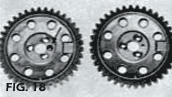
*Shown above right is a stock camshaft drive sprocket.
At left is the same sprocket with bolt and dowel pin holes drilled oversize to accept offset bushing in the advanced position.