Cam Degreeing
THE FOUR CYCLE ENGINE
Indeed, cam degreeing is simple, but first let's make sure you have a good understanding of the cam's function in the four cycle engine. You probably already know the four basic strokes of the four cycle engine: INTAKE, COMPRESSION, POWER, and EXHAUST. Each stroke represents one-half of a revolution of the crankshaft or 180 crank degrees. 4 cycles x 180° = 720° or two revolutions of the crankshaft. Two revolutions complete one sequence of the four strokes. The camshaft is connected via the timing chain and sprockets at a 1:2 ratio to the crankshaft and therefore revolves once for every two turns of the crank. Its purpose is to operate the intake and exhaust valves in the correct timing with the piston as it sequences thru the four strokes.
EARLY SLOW SPEED ENGINES
In the old days, the first four cycle engine had very short valve timing, but rightfully so because these were slow speed engines. The engineers of the late 1800's were only concerned with harnessing power of the gasoline and air explosions in an internal combustion engine to propel an automobile, hopefully, a little faster than a horse. They were merely concerned with getting the engines to run at slow speeds. Even in their wildest inspirations they would never have believed that a quarter or half century later, with better structures, these same engines would be revved five times as fast and produce many times more power.
EARLY SLOW SPEED VALVE TIMING
The old valve timing then was: Intake valve opens at T.D.C., and as the piston lowers, it draws in the fuel/air mixture; the intake valve then closes at (B.D.C.) hence, the intake stroke. The piston rises, with both valves closed to compress the fuel/air mixture. hence, the compression stroke. The spark plug fires and ignites the fuel/air mixture which drives the piston down to B.D.C. (again the valves are closed)... hence, the power stroke. Also, the exhaust valve opens at B.D.C. The burnt gases, due to their high pressure, virtually expel themselves, and the piston drives the last of the gases out; the exhaust valve closes at T.D.C.. hence, the exhaust stroke. These early engines had Oo overlap or no overlap whatsoever.
BRAZEN EXPERIMENTS WITH LONGER DURATION CAMS
By experimentation, the more progressive cam engineers of the 1910's and 1920's discovered that the midrange and high-speed power could be greatly improved by lengthened valve timing. The stretching of the intake valve timing allowed the engine to breathe deeper and take in greater amounts of air and fuel, thus creating a more powerful explosion in the combustion chamber. An important advantage gained from lengthened valve timing is that the greatly expanded gases are eliminated more efficiently and virtually by their own pressure. Unless these burnt gases are completely expelled from the combustion chambers, they will remain behind to displace and contaminate the incoming fresh fuel/air charge.
VALVE OVERLAP IS DISCOVERED
Lengthening of valve timing in the gasoline engine brought on accidental overlapping of the intake and exhaust valve events. (Both intake and exhaust valves are slightly open at T.D.C. In the early days, this unintentional overlapping was at first considered detrimental. But much later, it was discovered that a mild scavenging effect was obtained from the overlap event when the exhaust actually pulled some of the intake charge in.
ISKY INTRODUCES THE 5th AND SUPER SCAVENGING
In the early 1950's, Iskenderian introduced the first long duration cams which took full advantage of an extra long overlap period to super scavenge the combustion chamber and create in effect a fifth cycle in the four cycle engine. This required an optimum exhaust pipe system and at high speed the column inertia slug of exhaust gases helped pull the cool fuel/air mixture into and through the combustion chamber to produce substantially more horsepower.
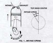
INTAKE OPENS - WHEN AND WHY - ON A MILD RACING CAM
In the cylinder and valve timing diagram (Figure 1) note that the intake valve begins opening 30°, before T.D.C. (top dead center) or before the piston actually starts on the suction (intake) stroke. This is purposely done to give the relatively slow opening valve a head start on the piston so at T.D.C. the valve will be well off its seat so as to offer little resistance to the incoming charge.
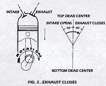
EXHAUST CLOSES - WHEN AND WHY
As the piston reaches and passes T.D.C., the exhaust valve is still slightly open and slowly closing. The burnt exhaust gases in the header pipe contain a great deal of column inertia. At high engine speeds, a noticeable scavenging phenomenon occurs when this column inertia actually helps draw in the intake charge during the short overlap period. At 30° past T.D.C. the exhaust valve finally closes (Figure 2).
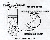
INTAKE CLOSES - WHEN AND WHY
The intake stroke continue as the piston moves downward, drawing the fuel/air mixture into the cylinder, reaches B.D.C. (bottom dead center) and starts again to rise in the cylinder beginning the compression stroke. Had the intake valve been prematurely closed at B.D.C. there would be a considerable loss in power at hi-speed since the intake charge having been in motion has built up kinetic energy and continues to flow filling the cylinder long after the piston changes direction. Some 70 degrees after B.D.C. the intake valve closes completing the intake stroke (Figure 3). Reviewing the intake valves' operation we see that its total opening period was 30° before T.D.C. + 180° to B.D.C. + 70° after B.D.C. for a total of 280 crankshaft degrees.
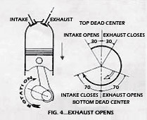
EXHAUST OPENS - WHEN AND WHY
The piston continues upward on the compression stroke compressing the fuel/air mixture to approximately 1/10 its original inducted volume. Just before reaching T.D.C. the spark plug ignites, and the flame gradually propagates through the charge. As the piston reaches T.D.C. the ignited mixture is expanding creating the "power stroke" and forces the piston downward once again. 70 crankshaft degrees before the piston reaches B.D.C. the exhaust valve opens to begin the exhaust stroke well before the power stroke has actually been completed (Figure 4). This seemingly loss of useful power is offset by the fact that the hot exhaust gases now leave the cylinder by virtue of their own pressure, thereby reducing the effort on the engine's part to expel the burnt gases on the upward stroke of the piston.
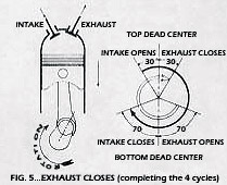
EXHAUST CLOSES - WHEN AND WHY
The piston completes its descent and once again rises in the cylinder to continue the exhaust stroke. Some 30o after reaching T.D.C. the exhaust valve closes once again. The total opening period of the exhaust valve then was 70° before B.D.C. + 1800 to T.D.C. + 300 after T.D.C. or 280 degrees of event (Figure 5). This completes one sequence of the 4 strokes. You should now understand the relation of piston movement to valve operation and are ready to learn the procedures for checking valve timing (Cam degreeing).
IS CAM DEGREEING NECESSARY?
Because Iskenderian Cams are manufactured with such high precision you can install them on the stock timing marks without any further checking; however, for those who wish to learn how to properly check and verify valve timing, we recommend the following procedure.
FINDING T.D.C. - CAM DEGREEING'S FIRST STEP
The purpose of checking or degreeing-in the camshaft in the engine block is to determine whether or not the camshaft is installed in the correct relationship or phasing with the crankshaft. However, the most important step in phasing a camshaft is finding absolute T.D.C. of the #1 cylinder piston. Trying to operate an engine without this vital marker is like trying to read a tachometer without an indicator needle. The T.D.C. marker is the all-important datum (tuning) point from which all ignition and valve timing is based. Quite often, we have observed racers at Bonneville, drag strips and circle tracks who neglected to provide themselves with a T.D.C. marker. All stock engines have a stationary pointer affixed to the block, and a T.D.C. marker on the crankshaft harmonic balancer. But, these racers lost the original pointer when they changed to an aluminum timing gear cover. Or, on supercharged engines, when they changed to a steel crankshaft drive hub, they lost the original T.D.C. marker. Now, here is their predicament: they now have no way of accurately setting their spark lead or valve timing. Had this engine been accurately calibrated for T.D.C. by utilizing the "Isky Positive Stop Method" while still on the bench, all doubts and frustrations would have been avoided. Thus, a possible winner became a loser.
It is a common error to miss T.D.C. by a few degrees due to the piston dwell at top center. Inasmuch as this inaccuracy will substantially affect subsequent timing, the following procedure is suggested to correct this error.
- Mount degree wheel on the front of the crankshaft. Now bolt a stationary pointer on the cylinder block (see illustration). Pointer can be made of metal strip or 1/4 inch steel rod.
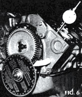
- Mount a dial indicator securely to the cylinder block. Now adjust dial so that at maximum piston rise the indicator sweep hand travels through approximately .300 of movement. The dial indicator contact point should rest on the center of the piston as shown in Fig. 6.
- Now to turn crankshaft over, use a long-handle wrench or lever so as to get an even, steady movement and not a jerky motion. The crankshaft should always be rotated in the normal running direction.
- Holding your thumb down on the No. 1 piston (to eliminate all lash), come up slowly to T.D.C. until you reach what you guess to be the middle of T.D.C. dwell. Set your degree wheel to read T.D.C. against the pointer.
- Now rotate crankshaft one more revolution and this time on the way up to T.D.C., stop exactly .200 (dial indicator reading) below the maximum piston travel. Now read the degree wheel; if for example, it reads 40 degrees before T.D.C., continue rotating slowly on up to T.D.C., over the hump and down the other side, keeping thumb firmly on piston. Watch dial indicator closely, and when it reads exactly .200 down from T.D.C., stop and note reading on degree wheel. If you have a perfectly split overlap, it should read 40 degrees after T.D.C. If it doesn't, you have not found exact T.D.C., therefore you must try again.
MAKING CORRECTIONS
Split the difference (your error in degrees) by moving the degree wheel radially on the crankshaft. After you have made the adjustment, come around with the crankshaft as before, stopping .200 below each side of T.D.C. When you get exactly the same degree readings .200 inch below each side of T.D.C., you have found absolute Top Dead Center. NOTE: The exact travel of .100-inch below T.D.C. is not important. Any check point between .100 and .500 will give good results, as long as you check each side of T.D.C. equidistantly.
POSITIVE STOP METHOD OF FINDING T.D.C.
The most practical way of locating T.D.C. is known as the positive stop method. No dial indicator is required for this procedure. First, let's see how it's done, utilizing the degree wheel.
- Fasten the degree wheel to the crank. Then, take a stiff 1/4-inch rod or similar material and sharpen one end to form a pointer. Attach this pointer so that it rests very close to the damper to eliminate parallax viewing error.
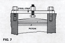
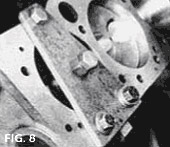
- Obtain a stout strip of steel about seven inches long and drill three 1/2-inch holes in it (see Figs. 7 & 8 for position of holes). This strip is placed across the center of the No. 1 cylinder bore and bolted on each end to secure it to the block. Caution: Be sure that the strip of steel is rigid enough so that it will not be deflected when the piston contacts the center bolt stop. Incidentally, the positive stop should be adjusted so as to stop the piston's upward travel at approximately .200 to .800 below T.D.C.
- Rotate the crankshaft in normal running direction (clockwise) until the piston crown lightly strikes the positive stop.
- Now, radially adjust and lock the degree wheel to the crankshaft at 40 degrees before T.D.C. at the pointer.
- Now rotate the crankshaft backwards to the positive stop. If the degree wheel reads' 40 degrees from T.D.C. you have hit Top Dead Center exactly, and the zero mark between the two 40-degree readings is absolute T.D.C..
- However if your readings were unbalanced, you will have to split the difference (your errors in degrees) by moving the degree wheel radially on the crankshaft. Then, try again until you get exactly the same degree readings against the positive stop on either side of T.D.C. NOTE: The lower the positive stop is located below T.D.C., the greater the degree readings will be. But, the results will always be accurate. T.D.C. always lies equidistant between the two positive stop readings.
FINDING T.D.C. ON YOUR HARMONIC DAMPER WITHOUT DEGREE WHEEL
Even without the degree wheel, you can and always should calibrate the T.D.C. mark on your harmonic damper when building or assembling a new engine. By using Step No. 3 and No. 5, each time you contact the positive stop, rotating both forward and backward, scribe a mark on the damper in line with the pointer. T.D.C. will be exactly between the two scribed stop marks. Carefully measure and scribe a permanent T.D.C. marker between these two stop marks. Remember the T.D.C. marker is the important datum (tuning) point from which all ignition and valve timing is based.
CAM DEGREEING PREPARATION
Having determined T.D.C., using your 1/2" travel dial indicator and degree wheel you are now ready to degree-in your camshaft. The two most common frustrations that people experience in cam degreeing are: 1. Checking at the valve. 2. Checking the valve-seat-timing.
CHECKING AT THE VALVE
Checking valve timing at the valve is not recommended because production tolerances on stock rocker arms can confuse your readings at the valve, whereas the direct motion of the lifter on the cam lobe will be the same for each lifter in the block. Another reason for never checking at the valve is that a rocker arm's theoretical ratio, usually 1.5:1, is true only at approximately mid (1/2) valve lift. The ratio varies from slightly more to slightly less than 1.5:1 through the lifting cycle, because the rocker arm continually varies its point of contact on the valve stem.
CHECKING VALVE SEAT TIMING - CLEARANCE RAMP ERROR
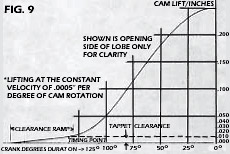
Checking the cam at the lifter is much more accurate but can still cause confusion if you try to check the actual valve seat timing, which involves checking on the clearance ramps of the cam lobe. The clearance ramps are the slow lifting portions of the lobe which provide a smooth, transition between the base circle and the cam flank on both the opening and closing sides of the lobe. On the clearance ramps, the first .010" or .015" of lifter movement is usually at the slow rate of .0005' per cam degree. In addition to gradually taking up the valve lash (necessary because of valve expansion and small deflections of the valve gear components), the clearance ramp provides the initial, gentle acceleration of the valve off its seat.
An example of these clearance ramps is described in the cam lift curve of Figure 9. As indicated in Figure 9, only the end of the clearance ramp directly adjacent to the cam flank is actually used to open and seat the valve, while the remainder is used to take up the clearance and compensate for small deflections or runout in the valve gear.
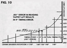
Since the clearance ramp rate of lift (velocity) is .0005" per cam degree, a slight error on your part of say .001" in checking the valve seat timing at a certain point on these clearance ramps, could account for 2 cam degrees (4 crank degrees) of error in determining the timing point as exemplified in Figure 10. And it is very easy to accumulate .001" error if the dial indicator's stem is not running parallel to the lifter (cosine error) or if you view the dial indicator's calibrations from an angle (parallax error) or if the cam bearings or tappet bosses are worn slightly. Obviously then to properly determine the position of your camshaft in the engine, the cam timing must be checked at a lifter height off the base circle where the velocity (rate of cam rise) is high enough so that small checking height errors of .001" or so will not result in gross degree wheel reading error.
ISKENDERIAN .050 LIFTER RISE METHOD
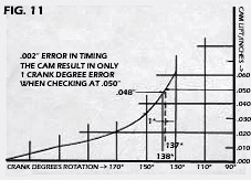
Many years ago a standard height was sought after by ISKENDERIAN engineers where all racing camshafts could be timed to give accurate results and in 1958 it was decided and later published in our top tuner's manual, "Valve Timing for Maximum Output" that .050" lifter rise off the base circle would be the accepted standard for our camshafts. This figure was ideal because it was not far enough off the base circle to confuse the engine builder when timing the camshaft, and it was high enough to show effective valve timing (a point where the valve is far enough open to pass an effective air flow). Also, the velocity (rate of cam lift) of most camshafts is approximately .004" per cam degree at .050' lifter rise. Therefore, a .002" error in checking height would only affect the degree wheel reading about 1 crank degree as shown in Figure 11. The ISKENDERIAN .050" lifter rise check has now become a standard in the racing cam industry.
DEGREEING THE CAM
CAM INSTALLATION
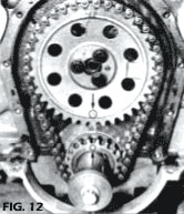
Before installing the cam in the engine block clean it thoroughly with solvent and air dry. Place a light coating of oil (preferably 10 Wt.) on the cam journals and the cam lobes you intend to check. Carefully revolve the cam while inserting it through the block, taking care not to score the cam bearings. Assemble the timing chain and cam sprocket while aligning the timing marks properly (Figure 12), and torque the cam sprocket bolt or bolts to the proper specifications. Always use a new timing chain when installing or timing a new camshaft. An excessively stretched chain can retard cam timing as much as four cam degrees. Shown is the procedure for aligning timing marks on a 427-cu.-in. Chevy; however, procedures vary from engine to engine. If you cannot find the timing marks, DO NOT remove the camshaft - consult a motor manual.
TIMING TAG CONTENT
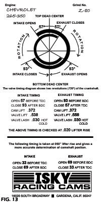
The timing tag you received with your camshaft shows the timing as determined by ISKENDERIAN engineers at a specific checking height off the cam's base circle. This height is indicated on the tag and is usually between .017"-.023" depending on the individual model cam you have. Checking the cam at this height would give you the actual valve seat timing, but as explained earlier this is not recommended. Instead, for more accurate results, use the figures taken at .050" lifter rise (also on the tag) to degree-in the cam. For example only, we will use the ISKENDERIAN 283-350 Chevy Z-80 cam in describing the proper cam-degreeing procedure (Figure 13). The valve seat timing of the Z-80 is intake opens at 57 and closes at 93 and exhaust opens at 93 and closes at 57 checked at .020 lifter rise. At .050" lifter rise because you are checking much higher up the cam flank the timing shortens to intake opens at 33 and closes at 69 and exhaust opens at 69 and closes at 33.
DIAL INDICATOR SET-UP
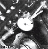
To begin your check of the camshaft, rotate the crankshaft until the No. 1 cylinder intake tappet is on the base circle (heel) of the cam lobe. Lubricate the tappet with light oil and check to see that it has free, unrestricted movement in the bore. Position the dial indicator stem parallel to the lifter in both planes, and preload the indicator's stem .050" - .100" on the tappet. At ISKENDERIAN to facilitate checking, we use an extended length tappet which brings the tappet to the proximity of the head gasket face and provides a level surface for the stem of the dial indicator (Figure 14). Rotate the crankshaft clockwise several times to determine the runout or eccentricity of the base circle. This should not exceed. 001 and should be centered equally on both sides of the zero on the dial indicator.
DEGREEING THE INTAKE LOBE
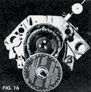
Rotate the crankshaft clockwise until .050" dial indicator movement is detected and read the degree wheel opposite the stationary pointer. It should read intake opening 33°, before T.D.C. (Figure 15). Record your reading and continue rotating the crankshaft watching the lifter reach full lift and begin to descend and stop the crankshaft's movement at .050" dial indicator reading before zero. The reading opposite the stationary pointer should be intake closing at 69° after B.D.C. (Figure 16). Record your reading and repeat your check of the opening and closing points of the intake cam to insure against human error in reading the indicator or degree wheel.
DEGREEING THE EXHAUST LOBE
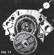
Remove the dial indicator and reposition it on the exhaust tappet of the same cylinder using the same setup procedure as before. Rotate the crankshaft clockwise until .050" dial indicator movement is detected and again read the degree wheel opposite the pointer. It should read exhaust opening at 69° before B.D.C. (Figure 17). Record your reading and again rotate the crankshaft watching the tappet reach full lift and descend and stop the crankshaft at .050" dial indicator reading before zero. Opposite the stationary pointer the reading should be exhaust closing 33° after T.D.C. (Figure 18). Record your reading and repeat your check of the exhaust lobe.
COMPARING YOUR READINGS TO THE TIMING TAG
The readings you have taken on the intake and exhaust lobes may very well be off 2 to 4 crankshaft degrees from the timing tag figures. If this is the case, the cause is probably slight errors in keyway location of the crankshaft or crank sprocket, or in the keyway or dowel pin hole location of the cam sprocket. These slight errors may be corrected by the use of two lsky inventions - the offset cam bushings or the offset cam and crank keys which will offset the camshaft with relation to the crank to bring the cam into phase with the crankshaft. They may also be used however, to either further advance or retard the cam to obtain the desired results. How do you determine an advanced or retarded cam position? This is explained in the following section.
RELATING VALVE OVERLAP TO THE TIMING TAG - WHAT IS A SPLIT OVERLAP?
Split overlap means that the intake and exhaust valves are split or open an equal distance at T.D.C. Overlap. Of course, this also means that the intake and exhaust tappets are split or equally off their cam's base circle at T.D.C. Overlap. The cam would be advanced if the intake tappet was open further at T.D.C., and retarded if the exhaust tappet was open further at T.D.C.
SINGLE PATTERN SYMMETRICAL CAMS
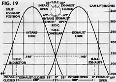
When the camshaft is single pattern (intake and exhaust cam profiles are the same) and the opening and closing sides of the lobes are the same shape (symmetrical) it is a simple procedure to check the phasing of the camshaft for split overlap or an advanced or retarded position. Figures 19, 20, and 21 are good examples of these conditions showing how the position of the intake and exhaust tappets at T.D.C. Overlap affect the opening and closing points of the tappets of the Z-80 camshaft. Figure 19 shows the intake and exhaust tappets equally off their base circles at T.D.C. Overlap and the timing diagram adjacent to the lift curve indicates the intake tappet opening at 33° B.T.D.C. and the exhaust tappet closing 33° A.T.D.C.
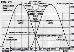
The intake opening and exhaust closing figures of the timing diagram are known as the "Top Timing" because they refer to the intake and exhaust timing points nearest T.D.C. Conversely, the exhaust opening and intake closing figures are known as the "Bottom Timing" because they refer to the intake and exhaust timing points nearest B.D.C. The fact that the intake and exhaust Top Timing is the same, and the Bottom Timing is likewise shows the cam is in the split overlap position. Figure 20 shows the camshaft in the advanced position with the intake tappet open much further at T.D.C. than the exhaust tappet. The timing diagram adjacent to the lift curve indicates that the intake tappet has opened 4° earlier and the exhaust tappet closed 4° earlier than when the camshaft was in the split overlap position. This accounts for why the intake tapet is open further than the exhaust tappet atT.D.C. To determine the amount the camshaft is advanced in crankshaft degrees, simply subtract the difference between the intake and exhaust Top Timing and divide by two. In this case 37° - 29° = 8° ÷ 2 = 4 crankshaft degrees of advance. To obtain the actual amount of advance or retard in camshaft degrees, simply divide the figure by two again, hence 4 ÷ 2 = 2° of cam advance. Figure 21 shows the camshaft in just the opposite condition being four crankshaft degrees retarded.
SINGLE PATTERN ASYMMETRICAL CAMS
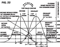
Thus far, we have seen how it is possible to use the cam timing diagram to determine the camshaft position in the engine with symmetrical cams only. But what of camshafts that are asymmetrical in shape? (The opening and closing sides of the lobes differ in profile). For the answer let us consult Figure 22 where we see that even though the tappets are equally open at T.D.C., indicating a split overlap, the timing diagram indicates the camshaft is five crank degrees retarded because of the extended closing ramp of the asymmetrical cam lobe. Therefore, it is evident that with an asymmetrical cam, the timing diagram cannot always be used to check for split overlap. A more accurate method then would be to check the theoretical "Centerline" (point of maximum lift) position of the intake and exhaust lobes. In Figure 22 notice that regardless of how the cam timing changes with the addition of higher closing ramps, the centerline of the intake lobe remains 110 crank degrees after T.D.C. and the centerline of the exhaust lobe remains 110 crank degrees before T.D.C. Therefore, we find that splitting the difference in crank degrees between the centerline of the intake and the exhaust lobes either side of T.D.C. is a more reliable means of phasing an asymmetrical cam.
THE SPLIT CENTER LINE METHOD
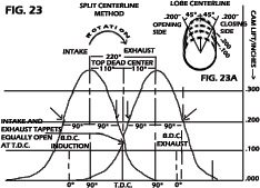
The camshaft is ground with a predetermined angular distance between the intake and exhaust lobes of the same cylinder. This distance is determined by the cam designer and verified through dynamometer testing of the cam design. This distance is known as the camshaft's "lobe centers" and is generally between 104° and 114°. This would be 208-228 crank degrees since crank speed is twice cam speed. Figure 22 exemplifies this distance at 220° with the centerline of the intake and exhaust lobes equally positioned on either side of T.D.C. 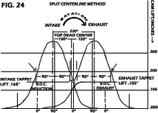 This is a very accurate method of phasing the camshaft because it eliminates checking down near the clearance ramps. An example of how to phase the camshaft using the "Split Centerline" method is given in Figure 23. From this illustration we see that if we take degree wheel readings at .200" tappet rise, on both the opening and closing sides of the cam lobe (Figure 23) the centerline of the lobe will be equidistant between these two points on the degree wheel. When the centerline of both the intake and exhaust lobes is determined, positioning them an equal number of degrees from either side of T.D.C. will give a split overlap. Of course, if it is desired to advance the camshaft one would merely move the centerline of the intake lobe closer to T.D.C. and thereby increasing the intake tappet lift and decreasing the exhaust tappet lift at T.D.C. This is exemplified in Figure 24.
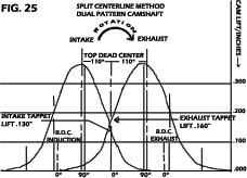
DUAL PATTERN CAMSHAFTS
The Split Centerline method can also be used to phase the camshaft if it is dual pattern (different intake and exhaust cam profiles). However, this may or may not give you a Split Overlap, depending on the actual difference in the two cam shapes. This condition is exemplified in Figure 25. Here we see that although the centerline of the intake and exhaust lobes are positioned equidistantly on either side of T.D.C. the amount the tappets are open at T.D.C. differs because of the longer duration exhaust lobe. Of course, the opposite could also occur, where the intake lobe was longer in duration and the intake tappet open further at T.D.C. Taking the cam in Figure 25 it would be best to run the camshaft in the "Split Centerline" position first to determine the performance of the engine and then either advance it slightly to a true "Split Overlap" or retard the camshaft even further to obtain the desired results.
CHECKING VALVE OVERLAP WITHOUT DEGREE WHEEL OR DIAL INDICATOR
When installing a camshaft, or when an occasion arises where it is necessary to make a check on valve timing and no appropriate instruments are available, the recommended Isky procedure is as follows:
- Insert the camshaft and mesh the timing gears on the stock marks. Do not as yet install the timing gear cover.
- Adjust the valve lash of the intake and exhaust valves of the No. 1 cylinder.
- Using a long wrench or lever, turn the engine over in the normal running direction. Use enough leverage to get an even, steady movement instead of a jerky motion. Rotate until the intake and exhaust valves of No. 1 cylinder are in the overlap position (both valves opened slightly). Stop exactly on T.D.C., which is marked on the harmonic damper.
- Now loosen and back off the rocker arm adjusting screws until the intake and exhaust valves are just barely closed. Lock the adjustment screws so that the intake and exhaust valves are at exactly zero clearance.
- Now turn the engine over exactly one revolution of the crankshaft to T.D.C. on the harmonic damper. You are now at T.D.C. on the compression or firing stroke.
- Take Notice! Now there is a large space between the rockers and valve stem tips. The space indicates the actual amount the valves were open at T.D.C. of the overlap period (less valve lash, of course).
- We will measure this gap space by probing with common feeler gauges of various thicknesses combined until we determine the gap space. After computing the gap, record the figures for both intake and exhaust in your notebook. If the amount of gap on intake and exhaust is exactly the same, you have a perfect split overlap.
AN EXAMPLE USING AN RPM 300 CAM
Advanced Cam Position: If your intake happens to come out with .100 gap, and the exhaust with say .080 gap, your cam is in an advanced position. In this position, the came will produce more low-speed power or torque. However, there might be a slight loss of power at high RPM.
Retarded Cam Position: If, on the other hand, the intake came out with .080 gap, and the exhaust at .100, your cam is in a retarded position. In this position, there will be some loss in low-speed torque and power, and probably some subsequent gain in high-speed power.
Split Overlap: If the intake and exhaust gap read out exactly even, or within .005 of each other, you have a split overlap. Generally speaking, all racing cams run best in the split overlap position. While there are exceptions to this rule, it is usually best for overall performance.